Electronics
Introduction
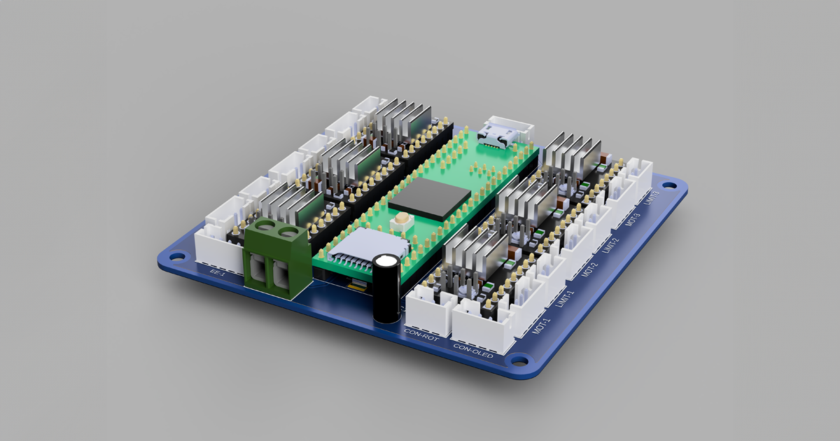
This documentation provides detailed insights into the custom electronics board designed for integrating various components with a Teensy 4.1 microcontroller. The board facilitates control and interfacing with A4988 stepper drivers, limit switches, a rotary encoder, an OLED display, a Bluetooth transceiver, and incorporates voltage regulation circuits.
1. Teensy 4.1 Integration
Description
The Teensy 4.1 is the core of this board, chosen for its high performance and compact size. It operates at 3.3V logic level, which is crucial for compatibility with other board components.
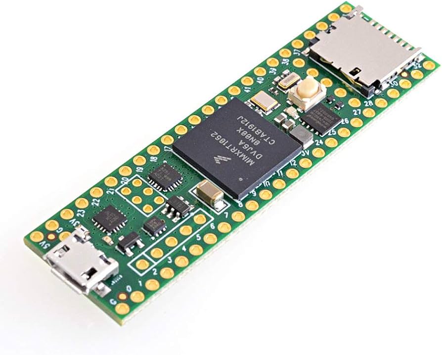 Teensy 4.1
Design Choices
- 3.3V Logic Level: Ensures compatibility with low-voltage sensors and modules.
- Compact Size: Allows for a more condensed and efficient PCB design.
2. A4988 Stepper Drivers
Description
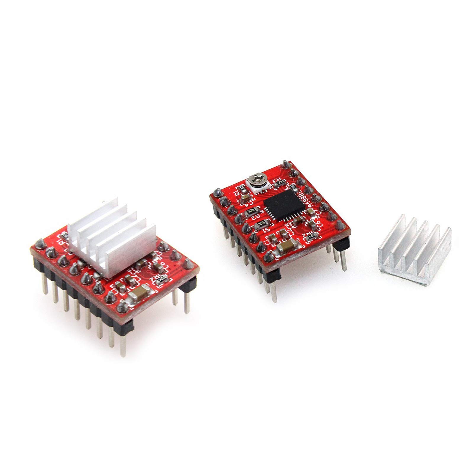
A4988 drivers are used for controlling stepper motors. These drivers are chosen for their reliability and microstepping capability, adjustable via jumpers.
Design Choices
- Microstepping Jumpers: Provide flexibility in motor control resolution.
- 12V Motor Supply: Selected to match the stepper motors’ requirements.
3. Limit Switches
Description
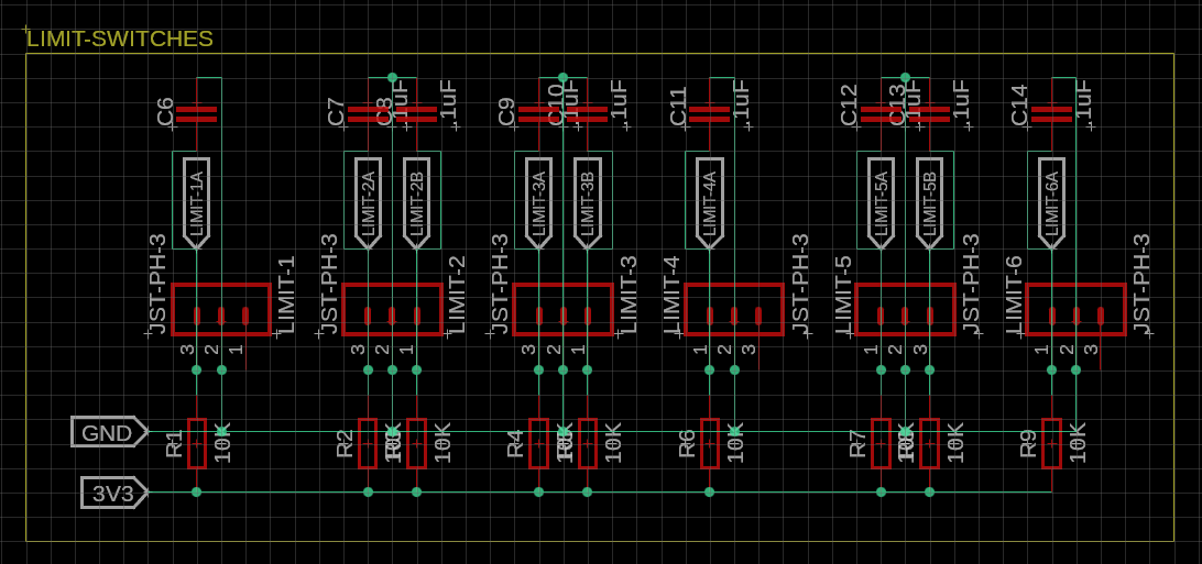
Limit switches are integrated for position feedback. Each switch includes analog debounce circuitry to ensure reliable operation.
Design Choices
- Analog Debounce: Reduces noise and false triggering.
- Position Feedback: Essential to avoid collisions.
4. Rotary Encoder
Description
A rotary encoder is used for user input, offering intuitive control for the system.
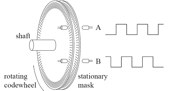
Design Choices
- User Input: Provides a simple interface for system control.
5. OLED Display
Description
The OLED display, using I2C communication, offers a user-friendly interface for displaying system status and information.
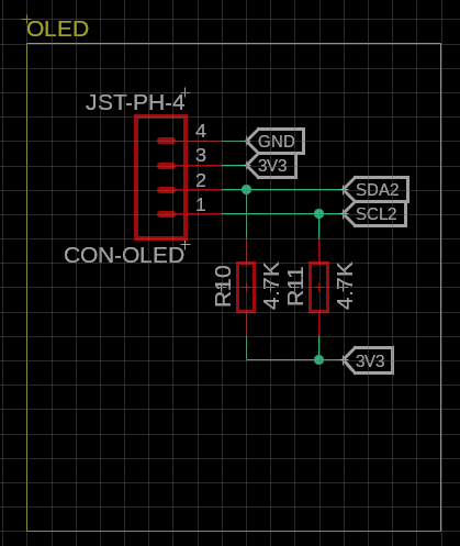
Design Choices
- I2C Communication: Simplifies wiring and conserves board space.
- User Interface: Enhances user interaction with real-time data display.
6. Bluetooth Transceiver
Description
A Bluetooth transceiver enables wireless communication, facilitating remote control and data transmission.
Design Choices
- Wireless Communication: Provides flexibility and convenience in controlling the board remotely.
7. Voltage Regulation
Description
The board features a voltage regulation circuit that steps down the 12V input to 5V for the Teensy and other components, which is further regulated to 3.3V for the Teensy’s operation.
Design Choices
- 12V to 5V Regulation: Matches the Teensy’s input voltage requirement.
- 5V to 3.3V Regulation: Built into the Teensy MCU.
8. PCB Design
Description
The PCB design is tailored to efficiently accommodate all components, ensuring minimal wiring and optimized space usage.
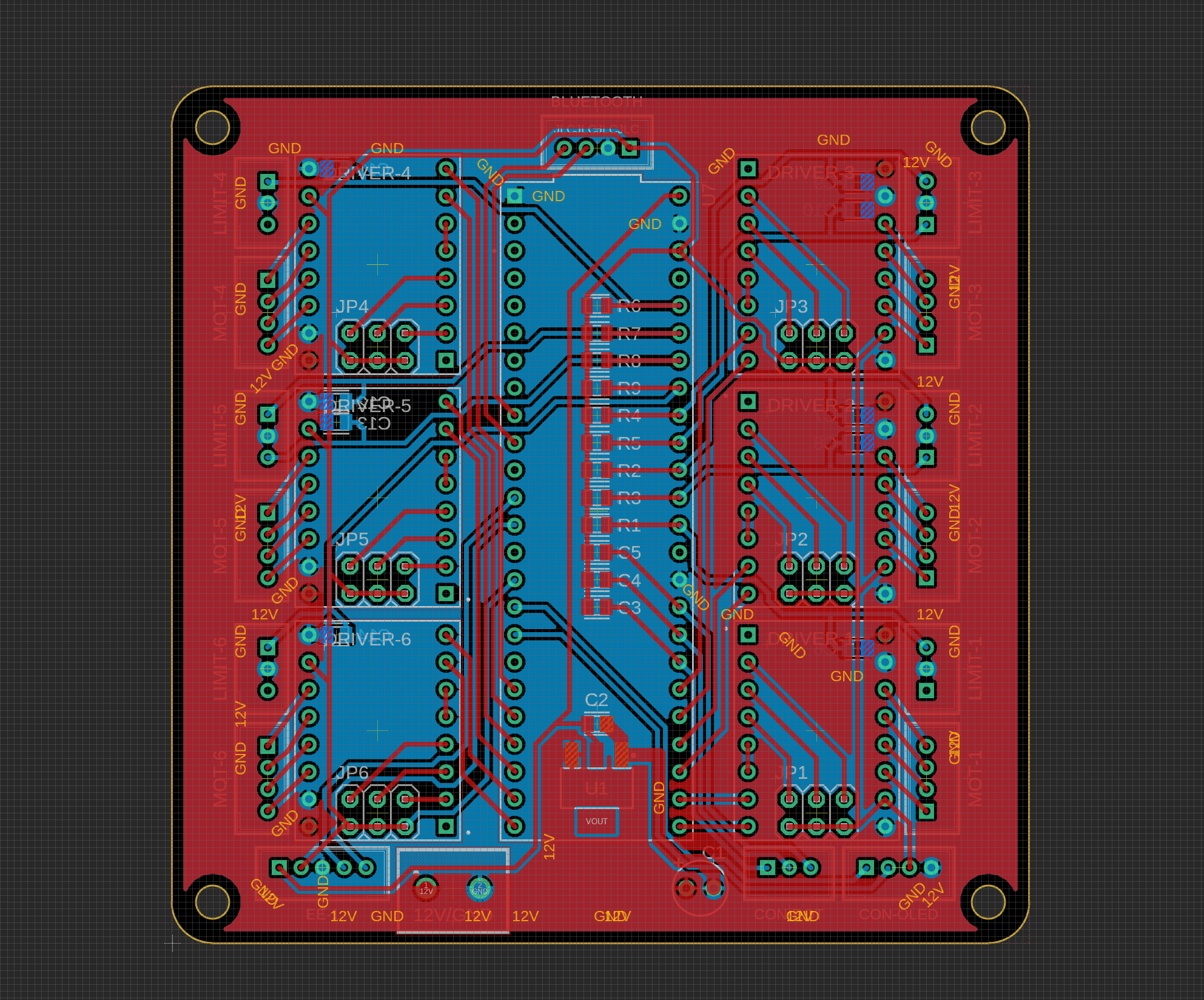
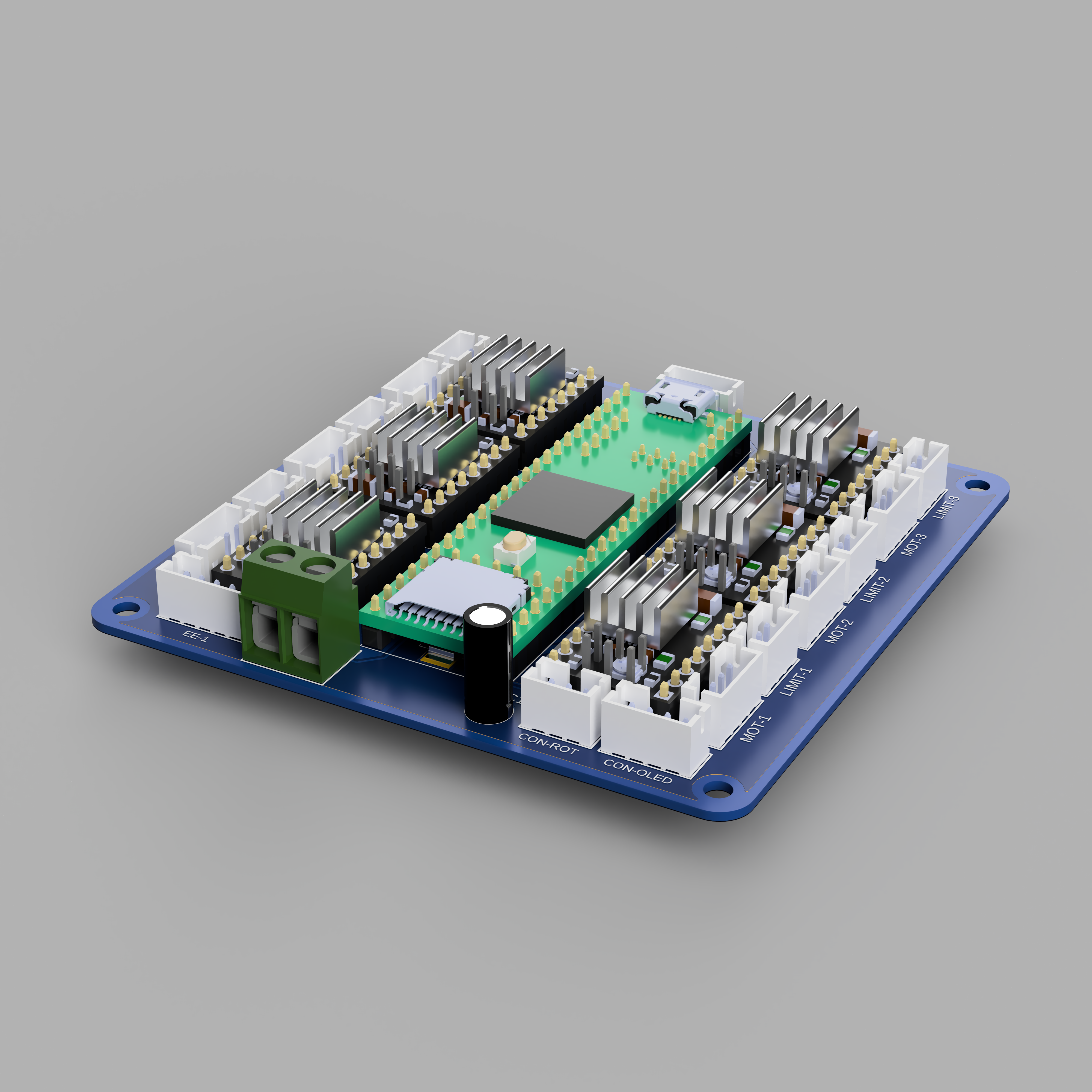
Design Choices
- Layout Efficiency: Minimizes board size while ensuring component accessibility.
- Component Placement: Strategically arranged to reduce interference and enhance performance.
Conclusion
This board represents a cohesive and thoughtfully designed solution for integrating various electronic components with a Teensy 4.1. Each section of the board is designed with specific considerations to ensure optimal performance, reliability, and user experience.